Surface Modification Techniques For Optimizing Adhesion To Automotive Plastics
Abstract
Automotive plastics with a low polarity, such as PE, PP, TPO, POM, PUR and PTFE typically require surface treatment when decoration is required.
Metallic surfaces may also require cleaning to remove low molecular weight organic materials prior to decoration. Once the above-mentioned interior and exterior grades of substrate surfaces are cleaned and activated, printing, gluing and painting are possible without the use of adhesion-promoting primers. This paper describes the latest innovations in three-dimensional surface treating technology for plastics finishing which address the need to advance adhesion properties, increase product quality, and achieve environmental objectives within the automotive industry. These innovations include advanced thermal and non-thermal discharge treatment processes for raising the polarity of surfaces to be painted, bonded, decorated, laminated, printed or to have tape applied.
Introduction
The utilization of plastics in the production of automotive parts has been steadily growing world- wide. Considering their key functional advantages, plastics have good performance characteristics, are lightweight, relatively inexpensive and are easy to manufacture. Among the various types of plastic which are used in automotive parts, thermoplastic polyolefins (TPO) have become the material of choice for exterior automotive applications such as bumpers and claddings. TPO and PP are the fastest growing due to their mechanical properties and their advantages relative to recycling.
As the use of propylene-based plastics has increased, so has the importance of coatings for these particular
substrates, which are inherently non-polar. Typically, surface coatings are used on plastic substrates for decorative and protective purposes. Because coatings are based on polar polymer materials, the adhesion of polar coatings to untreated non- polar substrates like TPO are difficult. The lack of adhesion can be attributed to poor surface wetting, poor solubility of the substrate and lack of bonding between an organic coating and the substrate. In general, solubility parameters have been used to estimate polarity of a material. For instance, the solubility of polypropylene is relatively low at 7.9 (cal/cm3).
Pre-treatment technologies for propylene- based polymer surfaces such as abrasion, acid etching, adhesion promotion primers and coatings, flame, corona discharge, plasma, wet chemical, and UV light treatment are among the historical options developed to combat these poor adhesion problems prior to applying surface coatings and decorations. Each of these treatments increases surface tension of the substrate by introducing polar function groups such as hydroxyl and carboxyl groups onto plastic surfaces, thereby allowing polar interfaces to better adhere.
Air and flame plasma processes have been used commercially for the modification of the wetting characteristics of automotive plastic parts. While TPO, for example, has the mechanical properties needed for automotive applications, they cannot be decorated or coated without surface modification. The most common pre-
treatment prior to painting and coating has been either been 1) the use of flame plasmas and/or high VOC-containing UV primers, as commonly used in Europe, or 2) the use of air plasmas, seen primarily in North America, as adhesion promoters. Flame plasmas are only as effective as the profile of the discharge, since sophisticated automotive part designs have deep recesses and accent grooves.
Because typical North American burner configurations are designed using steel ribbons and flats which create somewhat large orifices (and subsequently conical flames 2mm in diameter), the distance of the inner cone discharge tip from the burner face can be inherently and inappropriately short (approximately 3-5mm) relative to treating automotive part profile depths. Without the appropriate discharge velocity and density, these treatment devices can fall short of meeting critical automotive adhesion performance tests such as aging by humidity, thermal shock, resistance to chipping, fuel immersion and abrasion.
A critical design objective relative to discharge surface modification devices is to therefore optimize decoration and coating adhesion through the discharge of necessary energy and velocity to 1) create activated plasma species (modification will be dependent on the nature of the plasma gas) , 2) project the species (such as hydroxyl, carbonyl and carboxylic groups) to serve the varying contour and depth profiles of the automotive parts, and 3) modify the surface by several molecular layers deep so the bulk properties of the plastic is unaffected. This paper proceeds to describe recent improvements in the design of air and flame plasma discharge devices to meet these sub-objectives.
Background and Development Effort
During our effort to develop “enhanced discharge”, commercial-scale air and flame plasma treatment devices for automotive plastics, it was observed that the magnitude of treatment varied considerably as operating parameters such as power density (watts/ft2/min) and discharge velocity were varied.
Since the radicals most commonly associated with polymer surface modification are atomic hydrogen, atomic oxygen and hydroxyl radicals, this led to the hypothesis that the concentrations of these reactive species may increased under higher levels of power and velocity. Because chemical species and free radicals react with the surface, they improve the affinity to the adherent surface by forming chemical or electrical bonds. Furthermore, it is well known that accelerated ion bombardment causes topographical changes to the surface and thereby improves mechanical bonding. This can also create surface radicals through mechanical impact to the atomic structure.
These radicals can then participate in surface reactions and bonding.
With air and flame plasmas, it is important to note that ionization tends to occur at higher energies. Typically, for a reactive gas such as oxygen or hydrocarbons such as methane, 104 in 106 molecules form free radicals whereas only 1 in 106 ionizes.
Hence for reactive gases, the predominant treatment effect is from free radicals (see Figure 1).
Air and flame plasma discharges transport energy to break chemical bonds in polymer chains on plastic part surfaces. Broken polymer chains result in “dangling bonds,” which recombine with other reactive sites, resulting in significant molecular restructuring and cross-linking. The creation of dangling bonds allows for chemical “grafting” reactions to occur.
To optimize the surface modification effect of free radicals and ionic bombardment, high energy, enhanced discharge devices were developed and evaluated specifically for automotive plastics.
Equipment
The design of existing flame treatment burner technologies has heretofore been driven primarily by the evolution of BOPP film production, paper/paperboard production and web coating technologies. BOPP processing speeds of 450 – 500 mpm are now common as are coating speeds of 600- 800 mpm, and film widths can range up to 10 meters.
The improving performance of automobile plastics has also required improvements in air and flame plasma system treatment performance. Particularly with regard to flame systems, design impacts included better control of flame temperature and air gap at the burner, an increase in thermal output, burner cooling, better specific power (W/cm²) control, boundary layer penetration, flame stability, flame size and substrate dwell time within the flame. The predominant burner design being used in industrial applications are ribbon-type burners. They are designed for high heat release firing and are specified where a continuous flame is essential.
They utilize .015-.020 stainless steel ribbons and flats for flame retention and uniform heat distribution. Modification of the respective orientation, widths and depths of the ribbons and flats allows for changes in burner capacities, flame geometries and sizes. The burner bodies are typically constructed of cast iron. Control of ribbon burner energy output is primarily achieved by managing the air/gas mix, system air pressure and the burner design.
During our early efforts of evaluating ribbon and enhanced discharge burner designs for use with automotive plastics, it was logically observed that magnitude and longevity of treatment varied considerably as operating parameters were varied. Of particular note was the observation that in holding treatment speed of PP constant under varying power levels, surface energy levels as measured by dynes/cm can remain somewhat static under an increasing gap between the impinging flame and the PP substrate. Upon achieving a 40% increase in gap distance, dyne level decreased by an
average of 10% and progressively decreased with increasing gap distance. Moreover, the decrease in surface energy was marginally affected with a 12.5% increase in power level (see Figure 1). The same primary influence of gap on dyne level was confirmed with broad trial fluctuations in the power level and speed variables (see Figure 2). In this series of tests, it is important to note that a 50% increase in speed reduced dyne level an average of 10%.
This observation led to the hypothesis that development of a burner design consisting of a high velocity discharge flame may deliver more surface treatment period unit of time and effectively lead to treatment productivity improvements, particularly in the automotive industry. The potential to increase the gap distance between the burner and the substrate to be treated was also considered a possible outcome of development.
The primary development objectives of enhanced discharge burner technology included:
• Increased thermal efficiency
• Greater heat transfer (luminous flame radiative cooling effect)
• Increase treatment rate
• Port inserts which can be easily removed/cleaned in the field
There are two velocities which compose the shape and treatment efficacy of a burner flame – the velocity of the air/gas flow to/from the burner, and the formed velocity of the flame itself. The focus of control of these velocities was within the design of the combustion system and burner ports.
Relative to the development of an enhanced discharge air plasma equipment, the common denominator between all existing air plasma treatment systems is that the
power density required to deliver a given amount of treatment has heretofore been relatively the same among 3D part treatment systems. The main difference then, is how a particular manufacturer delivers the necessary power to the air plasma, at a particular system operating frequency. Current 3D treatment device designs operate at low frequencies and compensate for the inherently low power factor of the load by incorporating “power factor correction” devices into high voltage transformers. By doing this, the power supply is no longer required to deliver the kVA requirement of the load since the “power factor correction” device does.
With this type of system it is possible to operate at a higher overall system power factor, thus decreasing the kVA requirement of both the power supply and the high voltage transformer. However, this does not reduce the voltage requirement at the electrode(s) in the treater since the actual “load power factor” cannot be changed. Voltage stresses on the system contributes to reduced system life.
Although it can be seen from the previous discussion that it can be much better to operate at higher frequency than to correct for the lower frequency, as frequency is increased the electrode voltage requirement further decreases. This makes the gap between the plastic part and the electrode much more critical. A point will be reached where it can be difficult to maintain a gap of sufficient consistency and narrowness to insure consistent treatment across the part being treated. Furthermore, the electrode design
requirement for proper impedance matching grows smaller and more power is forced into less area, resulting in an inefficient air plasma with highly- filamentary discharges shooting from the electrode to the part rather than a smooth consistent glow.
With these parameters considered, we present the results of our development of air and flame plasma treatment devices which 1) generate significantly higher surface activation compared to existing air and flame plasma technologies, 2) generate smooth and high velocity plasma discharges which can reach
deep part crevasses, and 3) subsequently allows for effective gap maintenance from the part.
Experimental Design
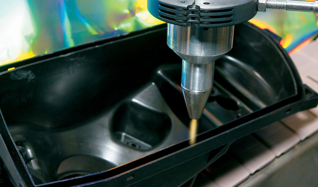
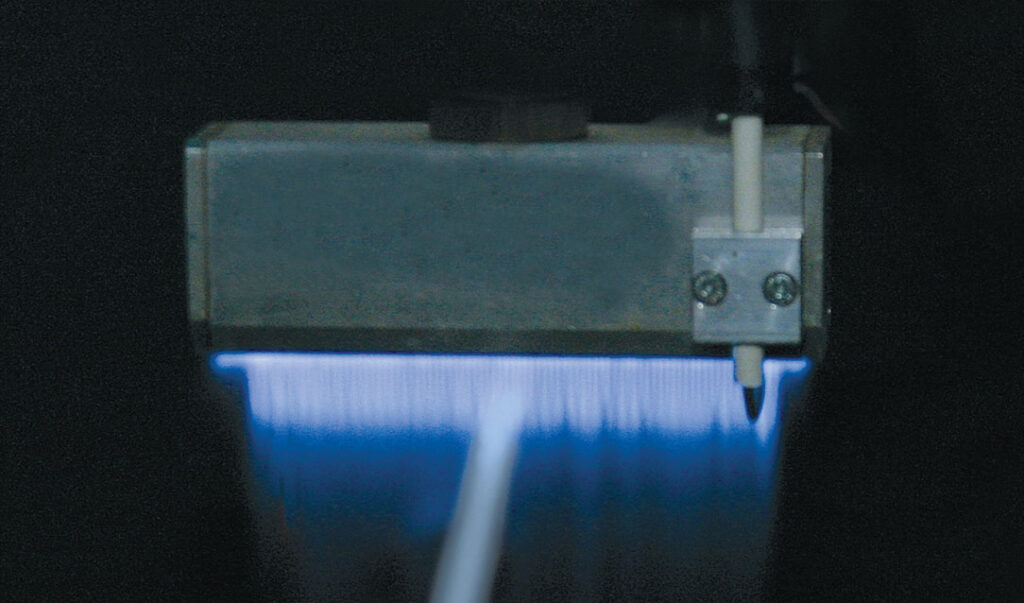
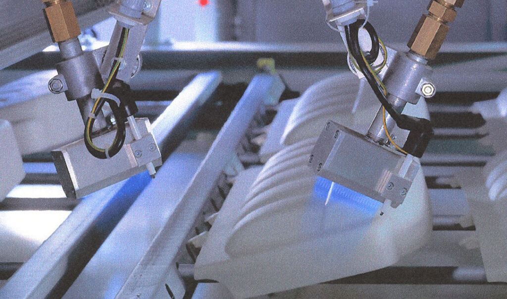
The initial R&D prototypes, and subsequent commercially-designed air and flame plasma treaters, were designed to provide homogeneous, uniform and enhanced discharges. The equipment was installed above a conveying apparatus in our surface treatment test lab. Photographs of the equipment discharges are shown in Figures 4.1-4.2 (air plasma) and 5.1-5.2 (flame plasma).
Appropriately designed processing discharges were concepted to either be combined by utilizing multiple heads or be manipulated by robotic devices to treat 3D automotive parts of various sizes and configurations, and could be operated at required speeds to adequately functionalize surfaces, contingent on the thermal properties of the part. Not shown in the above photographs are the control units and, relative to flame plasma, the process gas management system.
Prior to treatment, selected automotive plastics were analyzed relative to 1) their resident surface tensions using dyne solutions (formamide and ethyl cellosolve),
2) contact angles (de-ionized water utilized within a Tantec CAM-PLUS projection technique device), 3) the level of standard air plasma surface activation as characterized by conventional discharge, and 4) the level of standard flame plasma surface activation as characterized by ribbon burner discharge. These benchmarks are summarized in Table 1 below:
Subsequent treatment of these plastics were conducted using the “enhanced discharge”
air plasma and flame plasma units. Graphing of the relative results are found in Figures 6 and 7 below.
It will be noted that the flame plasma curves begin at a treatment speed of 100 fpm, as opposed to the air plasma curves whose treatment range begins at 25 fpm. This reflects the minimum speed required to provide measurable surface modification without thermal degradation among all studied materials.
Comparing the surface tensions of conventional air plasma discharges to the enhanced air plasma design (at 25 fpm treatment speed), it was noted that increases in tensions ranged from 5% to 28%.
Specifically, PVC, TPO and PP reacted most positively to the discharge design with increases in surface tensions ranging from 24% to 28%. ABS and HDPE showed significant improvements in wettability as well, increasing 13% and 16%, respectively. Modest improvement was seen in PC and PBT, averaging a 6% increase in wettability.
Comparing of the surface tensions of conventional flame plasma (ribbon-type) of the same BTU output to the enhanced flame plasma design, all materials registered increases in surface tension within the range of 4%-5%, averaging a 4.6% increase in wettability. Perhaps of more significance, the new enhanced flame plasma discharge design positively increased the distance between the inner cone discharge tip (prime treatment zone) and the burner face from an average of 4mm (ribbon-type) to nearly 10mm, increasing access to deeper automotive part profiles.
Conclusions
The air and flame plasma enhanced discharge equipment and the process parameters employed in this study are consistent with equipment and process improvements necessary for advancing surface modification results with automotive plastics versus the use of standard air plasma discharge and ribbon- type flame plasma designs. Although molding parameters and material variations will have somewhat of a determining effect on surface tension
variations from point to point on a given part, it was evident that the enhanced discharge
air and flame plasma designs significantly increased overall surface tensions, making these designs attractive alternative technologies for use in treating low polarity plastics whose use is accelerating within the automotive industry.
References
Rossman, K., “Improvement of bonding properties of polyethylene,” J. Polymer Science, 19, 141-144 (1956).
Prinz, E., and Forster, “New trends in corona technology for high and stable adhesion,” in European Film, Extrusion Coating, and Coextrusion Symposium Proceedings, , , TAPPI Press, 1995.
Raleigh, P., “Surface treatment: styles and options,” Plastics & Rubber Weekly, 1468, 12+ (Jan 1992).
Reneker, D.H., and L.H. Bolz, “Effect of atomic oxygen on the surface morphology of polyethylene,” J. Macromolecular Science, A10, 599-608 (1976).
Rideal, An Introduction to Surface Chemistry, 2nd Ed., MacMillan & Co., 1930.
Robinson, P.J., Decorating and Coating of Plastics (Rapra Review Report 65) , Rapra, May 1993.
Rosenthal, L.A., “Corona discharge electrode concepts in film surface treatment,” in ANTEC 1980 Proceedings, , 671-674, Society of Plastics Engineers, 1980.
Rosenthal, L.A., and D.A. Davis, “Electrical characterization of a corona discharge for surface treatment,” IEEE Transactions on Industry Applications, 1A-11, 328-334 (May 1975).
Rosseinsky, R., “Surface tension and internal pressure: A simple model,” J. Physical Chemistry, 81, 1578 (1977).

Figure 1
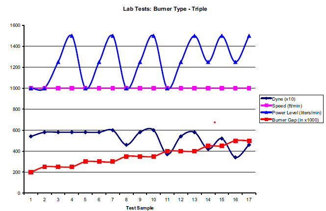
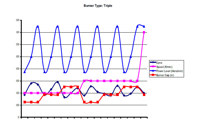
Figure 2
Figure 3

| Material Type | Pre-Treat Surface Energy (dynes/cm) | Pre-Treat Contact Angle | Conventional 3D Air Plasma (dynes/cm@25fpm) | Conventional 3D Flame Plasma (dynes/cm@100fpm, 5,000 BTU/in.) |
| ABS | 34-35 | 80° | 46 | 49 |
| PC | 45-46 | 72° | 56 | 59 |
| HDPE | 33-34 | 80° | 36 | 44 |
| PP | 29-31 | 90° | 42 | 47 |
| TPO (PP/Rubber) | 29-33 | 88° | 42 | 48 |
| PVC (plasticized) | 33-34 | 80° | 37 | 39 |
| PBT | 33-36 | 72° | 37 | 42 |
Table 1
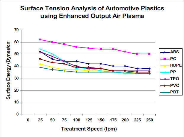
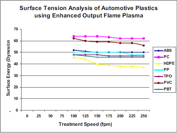
Figure 6
Figure 7
